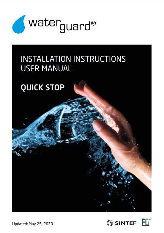
Components
| 1 | Wireless Central Unit | In this system, the unit doubles as both central unit and control panel |
| 2 | Solenoid valve (one or two) | Danfoss® solenoid valves in dimensions 1/2" or 3/4" |
| 3 | WTG-36C Wireless valve control | Activates the solenoid valve when a leak is detected by sensors or sensor wire/tape |
About the system
Waterguard® Quick Stop is a simple wireless system for stopping water leaks. It consists of a central unit that works together with wireless valve control(s).
The wireless valve control must be connected to the wireless central unit before use.
The unit is equipped with a delay function, by activating this the water will close after 4 hours.
NB: Wireless sensors, jack adapter, sensor tape and split cable are all mentioned in different contexts in this manual, in case you want to use these components as a supplement to Quick Stop.
The following components are combatible, but not included:
Wireless sensors, NRF number 5648275
Sensor Tape, NRF number 5648223
Jack adapter for flat sensor cable, NRF number 5648221
Split cable for 2 valves set-up, NRF number 5648199
The wireless valve actuator has an 230V AC 10 A for dishwashers, etc. In the event of a water leakage, the valve actuator will break the current voltage to the outlet. N.B. THIS SOCKET IS NOT INTENDED FOR USE WITH WATER HEATERS.
The unit features a 1,5 meter cable with a 3-poled contact that is to be connected to the solenoid valve. In case of 2 valves, use the split cable. The original screw for the solenoid valve contact should be used for split cable contact, while the included long screw is used to connect the valve control contact to the split cable male contact.
New functionality in this version of the wireless valve control
Safety Function
The wireless valve control has a built-in safety function to prevent the sensor cable from being pulled out of the valve control by mistake. Should this happen, a repeating 0.5 second audio signal will sound, the LED-indicator in the reset-switch will flash green and red - and the solenoid valve will close the water. When the contact is put in place, the alarm will stop and the solenoid valve will open the water again.
If the wired sensor port is not in use, this function is deactivated.
If the wired sensor port is not used, this function will be deactivated.
Should the sensor wire by mistake be connected and not intended for use, the safety function can be reset. This is done by cutting the power to the valve control and replacing in the socket - without the sensor wire in place.
NB: Only the contact itself is monitored. If the sensor wire should break, it will not be reported with this function!
Auto-exercising valve
The wireless valve control features a function that makes the valve quickly open and close regularly. This prevents the valve to get stuck from particles in the water.
The exercise sequence runs for 1 second after the power connection, and the sequence is so fast that the water flow will not be affected. The unit comes programmed with one exercise sequence every 24 hours. It can be reprogrammed to exercise once a week or not to exercise at all.
Reprogramming the exercise sequence is done this way:
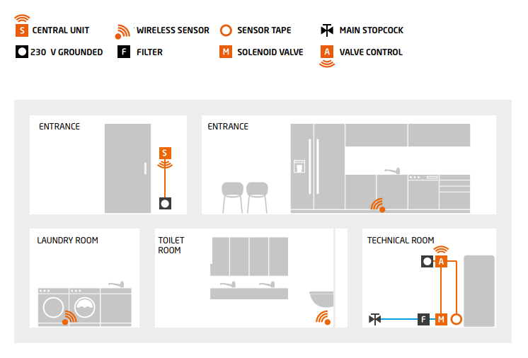
Push and hold the Reset-button before the unit is inserted into the socket. The Reset-button is hold down, and after 20 seconds and audio signal will sound. The signal will loop in 3 different steps until the Reset-button is dropped - right after the desired sequence, based on the following audio signal.
If the Reset-button is dropped after 1 beep, the unit will exercise every 24 hours.
If the Reset-button is dropped after 2 beeps, the unit will exercise every 7 days.
If the Reset-button is dropped after 3 beeps, the unit will not exercise.
To check the exercise status, follow this procedure:
Pull the valve control out of the socket and wait approximately 10 seconds, then put it back into the socket. The subsequent audio signal should correspond with the chosen exercise frequency. To change the chosen exercise sequence, repeat the intial procedure.
NB! When exercising, the units 230V socket will get a 300 Ms, power interruption. Under special circumstances this can make some connected devices change their operational status.
Should this happen, it is not considered a fault on the Waterguard valve control.
Connecting/registrating wireless units
Wireless unit(s)
Prior to installing, the wireless unit(s) must be connected/registrated with the central unit
Connect the power cord to the wireless central unit.
Insert the wireless valve control in a socket, and connect the solenoid valve contact to the valve.
Open the wireless sensors and insert the batteries. Do not put on the lid again.
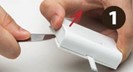
1. On the central unit, press and hold RESET for about 2 seconds. The unit first emits a beep, then 2 beeps. The unit is now ready for connection with the wireless central unit.
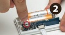
2. On the central unit, press and hold RESET until 2 audio signals are heard. In a couple of seconds, the wireless unit(s) will be connected, and will emit audio signals. The signals indicate successful connection.
If wireless sensors are part of your system, go to part 3.
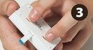
3. Repeat part 1.
4. Push and hold for 1 second the small button on the first wireless sensor's circuit board. The central unit will emit audio signals, and a small diode will blink fast for approximately 1.5 second. This indicates a successful connection.
5. If more wireless sensors or valve controls are to be connected, repeat the above described procedure.
The central unit will store the sensors in the order they are connected. Thus, in case of alarm the central unit will indicate which sensor was triggered by emitting the number of audio signals corresponds with the order in which the sensors were connected. If several units sound the alarm, the last of them is the one that corresponds with the central unit. In case a sensor is connected more than once, the sensor will get a new ID-number in the central unit.
With several sensor connections with the central unit, you may get a large number of audio signals. To clean this, it is possible to edit the ID order.
Editing the ID order:
On the wireless central unit, press and hold RESET for approximately 7 seconds, until you hear 5 short beeps. Then, by connecting previously connected units, these will have new ID's that starts with 1.
Installation instructions
Wireless Central Unit/Control Panel
1. The wireless central unit should be installed in a hidden wall box for electrical couplings, so that the included power supply can be placed inside the wall box. This gives a good-looking installation and ensures the units are continuously connected to power.
The power supply can also be placed inside the wall box of one of the underlying switches. In this case, the wires should be routed out from the frame. A multibox can also be used, for example Elko Multibox rør/PFXP (El number: 12223740)
2. The included external power supply may be used instead of the internal one, but if the external power supply is unintentionally pulled out of the socket, the wireless units will no longer work.
Solenoid valve
1. Solenoid valve is best mounted on the cold-water intake, after the main stopcock. If a fire hose is installed, the solenoid valve must be mounted after this outlet.
2. A filter must be installed if dirt or particles are present in the water.
3. Make sure that sealing material does not enter the valve when mounting.
4. The solenoid valve may be mounted horizontally or vertically. When mounted horizontally, the coil must not face down. By vertical mounting the electric contact must always be on top of the coil.
5. The solenoid valve must be mounted in the proper flow direction, indicated on the valve by an arrow.
Wireless Valve Control and Sensor Tape
1. The valve control is installed in a 230V rounded socket close to the solenoid valve and the area to be monitored
For installation without sensor wires, go to part 5
2. Connect the Jack-plug to the valve control, and secure to the ground with cable shoes.
3. The sensor tape is mounted in the Jack-contact. The blue plastic tip at the end of the tape must face away from the metal contact at the end of the Jack connector.
4. Remove the protective paper from the back of the sensor tape. Fasten the sensor tape to the floor/underlay where leaked water may gather.
5. The solenoid valve contact on the valve control is connected to the valve, with the screw tightened (by hand) to fasten the contact to the valve coil.
Wireless sensor
On floor
May lie loose on the floor, underneath a dishwasher, refrigerator or similar. Remove the attached wall bracket so that the sensors come in contact with the floor. Insert batteries according to instructions. The loose sensor tip can be folded under the sensor before it is placed on the floor.
On wall
Using the included bracket, you can easily mount the sensor on the wall. Fasten the bracket so that the sensor tip reaches down tot he floor. Insert batteries according to instructions. Slide the sensor tip into the opening in the bracket and put the sensor in place.
Using sensor tape
Open the wireless sensor by removing the top lid and remove the batteries. Pull out the existing flat sensor tape, and slide the new sensor tape all the way into the contact - with the blue side facing down. Make sure that the locking pin in the sensor fits the hole in the sensor tape. Insert the batteries and put the lid on. On the sensor tape, remove the protective paper and fasten the tape to the floor. Cut the sensor tape at the desired length (by cutting the tape in two parts, it can be used with 2 sensors). Finally, test the tape function by wetting the sensor points and check that the alarm is triggered.
Start and test
Test the system before it is placed out by operating the central units ON/OFF function; The valve should emit a distinct clicking sound when being powered from the valve control. Also test the wireless sensors by moistening the sensor points on the sensor tape. When the wireless sensors emit an alarm, the central unit - when in ON-mode, go to OFF - and the valve will close. Reset the valve by pushing RESET twice. If the sensor tape on the wireless valve control is activated, the RESET button on the valve control must be pushed once before the central unit can be reset by pushing RESET twice.
To reset the system and open the water, the cause for the initial alarm must first be eliminated.
NB: After system testing, the owner/user must get a proper briefing on how to use the system.
1. Install all units in their proper place, and connect them to power. No audio signal should be heard, apart from the start-up sound.
2. Open a tap to let the water flow. This is to control that in the following test the valve really stops the water from flowing from the open tap.
3. If you use the sensor port on the wireless valve control:
Test the safety function for the sensor cable by pulling it out.
- A brief 0.5 second repeating signal will sound.
- The LED indicator in RESET button will flash red and green.
- The solenoid valve will close the water, and the tap-water will stop flowing.
- The water should return when the sensor cable is inserted again.
4. With a wet cloth, moisten one of the sensor points on the tape.
5. The valve control will now indicate a leak, with a beep repeating about every second.
The LED indicator in the RESET button will flash red, and the solenoid valve will close the water.
6. Check that water has stopped flowing from the tap.
7. Push the RESET button once to cancel the audible alarm. The water should remain closed.
8. Wait for 1 minute while wiping the moist sensor point dry.
9. Now, cancel the alarm by pushing RESET button twice.
The audio signal in the central unit will stop, and LED-OFF will change to LED-ON.
10. Make sure the water starts flowing again from the open tap.
11. Moisten the sensor point on the first wireless sensor. The drop in the Waterguard logo on the wireless sensor will flash red when the sensor point is wet, and an alarm signal is sent.
12. The tap will close for water, and the central unit will emit the number of beeps that corresponds with the related wireless sensor. Wipe the sensor point dry.
13. Reset the wireless sensor by pushing RESET twice.
14. Make sure the water start flowing from the tap.
15. Repeat the procedure with the rest of the sensors, and make sure the sensor points are wiped dry after the tests.
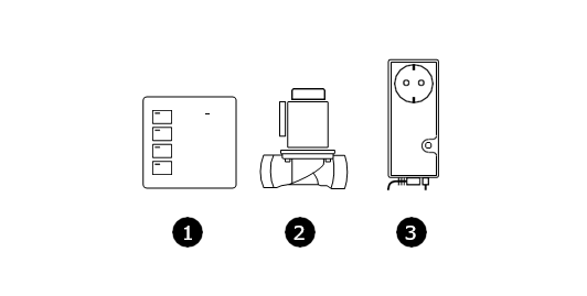
Principle sketch
User manual
In case of alarm - If additional components are installed
1. The system may warn in two ways:
2. Water leaks registered by wireless sensors will only be warned on the wireless control panel.
3. Water leaks registered by the sensor cable from the valve control, will be warned both on the valve control and on the control panel.
4. The leak alarm from wireless sensors can only be reset on the control panel. Leak alarm from the sensor cable from the valve control must be reset first on the valve control, then on the control panel.
5. If the water has hit the valve control's cable, the valve control will emit repeating beeps for about 1 second and the RESET button will flash red. The solenoid valve has now closed the water supply. The central unit will indicate water alarm with audio signals and LED OFF flashing.
6. If water has hit a wireless sensor, only the control panel will give alarm with sound and LED OFF flashing. At the same time the solenoid valve will close the water supply.
7. The cause is either a water lead or other factors like washing, etc.
8. Localize the water leak/spill and dry off the water if possible.
9. The audio signal on the units can be stopped by pushing the RESET button once. The solenoid valve will still be closed.
10. In case of a water leak, close the main stopcock and contact a plumber.
11. When the damage or spill is fixed, the wet part of the sensor must be dried properly off with a dry cloth.
12. Push the RESET button and the light will go from red to blue. The solenoid valve will open.
System Test (at least twice a year)
1. Open a tap and let the water flow.
2. With a wet cloth moisten the sensor point on a sensor. The alarm will be triggered and the water will close.
3. Make sure the water in the open tap stops flowing.
4. Dry the sensor properly with a dry cloth. Push the RESET button on the central unit to cancel the alarm. The alarm signal should stop and the LED should go from red (OFF) to blue (ON). The valve should open again.
5. Repeat this procedure on all wireless sensors, and on the sensor cable from the valve control - if this is used. NB: When the sensor port in the valve control is activated, the valve control itself must be reset before the central unit can be reset.
Battery change
The included sensor batteries has an expected lifetime of approximately 5 years.
Battery change is recommended after maximum 5 years. This is because wireless sensors with low battery voltage can have problems communicating with the central unit if installed far away from this.
The central unit will warn about low battery voltage with audio signals only. It will remain in its initial status without giving an alarm or close the solenoid valve.
The number of audio signals from the central unit will coincide with the sensor's given number at registration. The alarm will repeat every 25 seconds.
On the central unit, reset the "low battery voltage" with short push on RESET. Remember to take note of which sensor is triggered (by listening to the initial alarm signal) BEFORE you do this:
- Remove the sensor from the wall bracket by pulling the sensor approximately 5mm upwards and then straight out from the bracket.
- Remove the batteries and insert new with the same specs. Push the small, red button (marked with red in the picture) and check that the LED on the right side of the button starts flashing. Put the lid back on the sensor.
- Test the sensor (also, see part 4 below). Place a moist cloth (or a wet finger) on one of the sensor points. This should release the alarm. Thoroughly, wipe the sensor point dry afterwards.
- Put the sensor back in the bracket on the wall. It is a good idea to repeat the test with the sensor back on the wall, by moistening the sensor cable.
See attachments for form for confirmed installation.
Comments
0 comments
Please sign in to leave a comment.