
Version: 05.25/2020
This guide applies to all Adapter versions:
| Adapter 1 | |
| 5648184 | WG Adapter 1 w/power cut 1/2” |
| 5648185 | WG Adapter 1 w/power cut 3/4” |
| 5648556 | WG Adapter 1 w/power cut 1” |
| 5648557 | WG Adapter 1 w/power cut 1 1/4” |
| 5648558 | WG Adapter 1 w/power cut 1 1/2” |
| 5648559 | WG Adapter 1 w/power cut 2” |
| 5648284 | WG Adapter 1 w/power cut, without valve |
| NC systems | |
| 5648187 | WG Adapter 1 w/power cut, NC 1/2” |
| 5648189 | WG Adapter 1 w/power cut, NC 3/4” |
| 5648298 | WG Adapter 1 w/power cut, without valve, NC |
| Adapter 2 | |
| 5648186 | WG Adapter 2 w/power cut 1/2” |
| 5648561 | WG Adapter 2 w/power cut 3/4” |
| 5648562 | WG Adapter 2 w/power cut 1” |
| 5648563 | WG Adapter 2 w/power cut 1 1/4” |
| 5648564 | WG Adapter 2 w/power cut 1 1/2” |
| 5648565 | WG Adapter 2 w/power cut 2” |
| 5648566 | WG Adapter 2 w/power cut, without valve |
| NC systems | |
| 5648188 | WG Adapter 2 w/power cut, NC 1/2” |
INCLUDED COMPONENTS
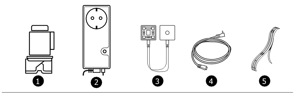
| 1 |
SOLENOID VALVE (1 or 2) |
Danfoss solenoid valve comes in 1/2” to 2” dimensions |
| 2 |
VALVE CONTROL WTG-36A (NC) |
Monitors leaks and activates solenoid valves when the sensor detects a water leak |
| 3 | SPLIT CABLE (IN VERSIONS WITH 2 VALVES) |
Cable that splits so that 2 valves can be controlled |
| 4 | JACK-ADAPTER |
For connectring sensor tape to the valve control |
| 5 | SENSOR TAPE | Sensor tape (3 m) with glue. To be taped to the floor/underlay where water may gather |
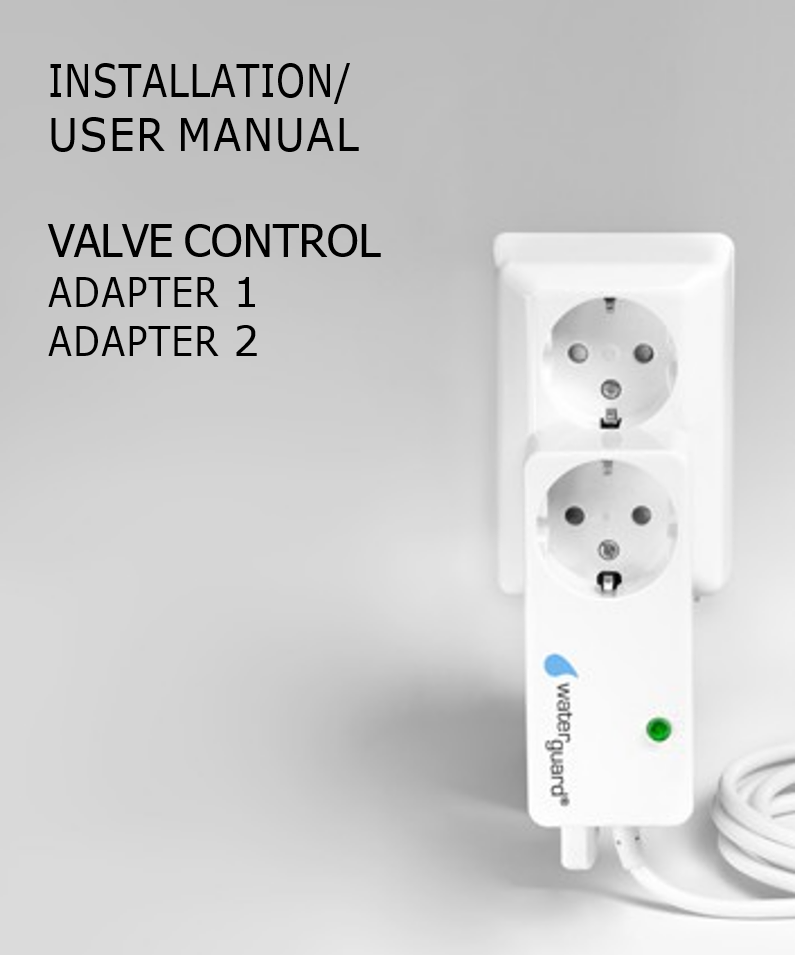
The valve control
Waterguard valve control is a compact solution with all necessary electronics placed inside the unit. This is going into a grounded socket.
The unit has a 230V AC 10A contact for use with dishwashers etc. In case of a leak the valve control will cut the power for this contact.
NB! THIS CONTACT IS NOT TO BE USED WITH WATER HEATERS. (REF. NEK 400 - Norsk Elektroteknisk Komite (NEK))
The unit uses a 1.5 meter cable with a 3-poled contact to be connected with the solenoid valve. When two valves are to be connected, use the split cable with the included long screw. Using this screw, connect the valve control contact to the split cable male contact.
NEW FUNCTIONALITY IN THIS VERSION
Compared to earlier models, this one has several new functions:
SAFETY FUNCTION
The wireless valve control uses an internal safety function to prevent extracting the sensor cable by accident. Should this happen, a repeating 0,5 second signal will be heard, the LED indicator in the reset switch will flash with a red light and the solenoid valve will close the water. When the contact is put in place again, the alarm will stop and the valve will re-open the water.
NB! Only the contact itself is monitored. A broken sensor thread will not be reported by this function!
AUTO-EXERCISING VALVE
The wireless valve control is equipped with a function that automatically exercises the valve. This will prevent the pilot valve from being stuck due to particles in the water.
1 second after it is powered, the unit will go through an exercising sequence where the pilot valve will open and close very fast, without influencing the waterflow.
The unit comes pre-programmed with one exercising cycle every 24 hour.
This can be changed to the following frequency:
1 time every 24 hour - 1 time every week - no exercising of the valve.
Reprogramming the exercising cycle:
Hold in the Reset-button before the unit is powered, and keep holding it. After 20 seconds an audio signal/ beep will be heard, and this will loop in 3 different steps until the Reset-button is released after the sequence you prefer.
If the Reset button is let go after 1 beep, the valve will exercise every 24. hours. If the Reset button is let go after 2 beeps the valve will exercise every 7. days.. If the Reset button is let go after 3 beeps the valve will not excersise.
To control the excersise status:
Disconnect the power, and after 10 seconds put contact back.
The unit will now emit a number of beeps that correspond to the chosen exercise frequency. If you wish to change the exercise cycle, repeat the above explained programming sequence.
NB! When exercising is performed, the voltage will be cut in the units 230V port. This cut lasts approx. 300 ms, and might cause connected appliances to change their operating status. Should this happen, it is not regarded a error on the valve control from Waterguard.
INSTALLATION INSTRUCTIONS
SOLENOID VALVE
The solenoid valve must be installed by a professional plumber, in frost-free environments.
- The solenoid valve is preferably mounted on the cold water intake after the main stopcock. If fire hose is installed, the solenoid valve MUST be installed after that.
- Filter MUST be installed where water can be contaminated by dirt or particles.
- Make sure sealing material does not enter the valve by assembly.
- The solenoid valve can be installed horizontally or vertically. When installed horizontally, the electric coil must never face downwards. When mounted vertically, the electric contact must always be on top of the coil.
- The solenoid valve must be installed in the direction of waterflow, see arrow on the housing.
WIRELESS VALVE CONTROL ANS SENSOR TAPE
-
The valve control is installed in a 230V grounded socket close to the valve and the monitored area
-
Connect the Jack-adapter to the valve control, and fasten it with cable fasteners to the floor
-
The sensor tape is fastened to the Jack-adapter with the blue tape-strip on the end.
-
Remove the protective cover from the sensor tape underside, and glue the tape to the floor/underlay where water from a leak may gather
-
Connect the solenoid valve contact to the valve control using the enclosed screw. Tighten carefully to slightly squeeze the contact to the valve coil.
START-UP AND TEST
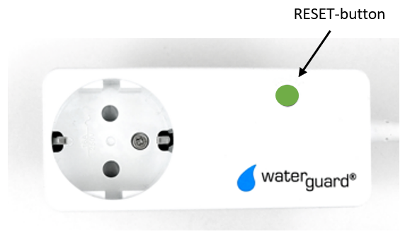
- Check that no audio signals is heard and that the LED indicator in the RESET button lights green.
- Open a tap so that the water runs. In the following tests, check the tap to see that the valve has closed.
- Test the safety function for the sensor contact by pulling the plug out.
- A brief 0.5 sec. repeating signal is heard.
- The LED indicator in the RESET button will flash red and green, and the solenoid valve will close. Check that this stops and the water runs again when the plug is put back in the contact.
- With a wet cloth, moisten one of the sensor points on the sensor tape
- With repeating alarm signals every second, the valve control should now indicate a leak. The LED indicator in the RESET button should light red, and the solenoid valve will close the water.
- Check to see that the water has stopped running from the open tap.
- Carefully dry off the moistened sensor point.
- Wait one minute before resetting the alarm by pushing the RESET button. The alarm signal will now stop, and the LED indicator in the RESET button will light green. The valve will open for water again.
- Check that the water keeps running from the still open tap.
- Close the tap.
NB! After testing the system, make sure to instruct the user properly.
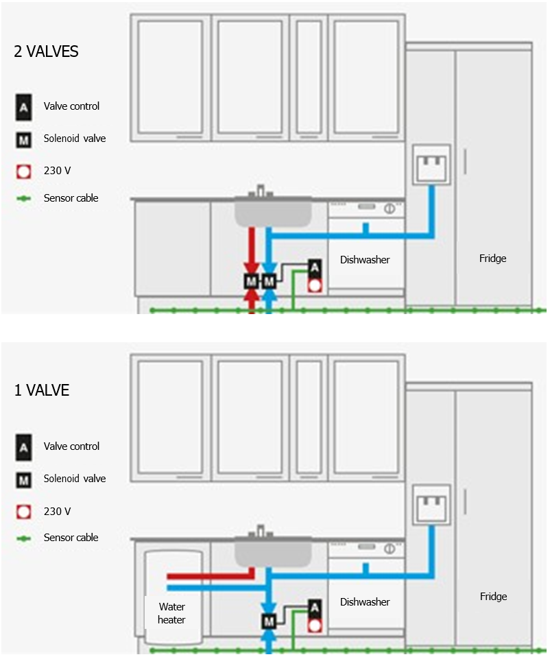
PRINCIPLE DRAWING
USER MANUAL
The RESET button will light green by normal circumstances. In case of alarm, the indicator will light up red. Together with an audio alarm, this indicate that the leak sensor is activated.
IN CASE OF ALARM
- If water has entered a sensor, the valve control will emit an approx. one second repeating alarm signal. The RESET button will light red, and the solenoid valve has closed the water supply.
- The cause is either a leak, or someone has been spilling water while washing.
- Localize the leak or spill, and dry up the water if possible.
- The alarm signal can be stopped by pushing the RESET button once. If the sensor is still wet, the RESET button light will stay red.
- If a real leakage has occurred, close the main stopcock and contact a plumber.
- When the damage/spill is fixed, the moist part of the sensor must be dried off carefully.
- Push the RESET button and the light will change from red to green.
TEST THE SYSTEM (minimum twice per year)
-
Open a tap to leave the water running.
-
With a wet cloth moist a sensor point. The alarm will go off and the water supply will be closed.
-
Make sure the water has stopped running from the open tap.
-
Carefully wipe the sensor dry. Push the RESET button to cancel the alarm. The audio alarm will now stop and the light in the RESET button will light green. The valve will open for water again.
Comments
0 comments
Please sign in to leave a comment.