This information is valid for these Smart Stop variants:
1 valve 1/2" (ART NO 5648191)
1 valve 3/4" (ART NO 5648193)
1 valve 1/2" NC (ART NO 5648195)
1 valve 3/4" NC (ART NO 5648197)
Included components
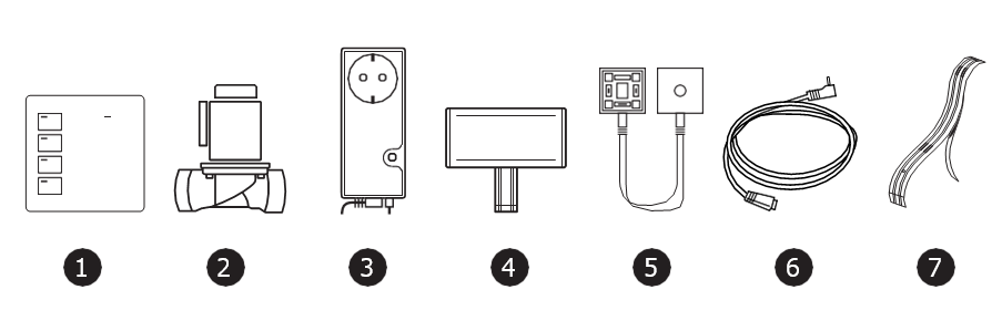
1. CENTRAL UNIT WTG-38A (ART NO 5648329)
The unit doubles as central unit and control panel.
2. SOLENOID VALVE (1 OR 2 PCS.)
Danfoss (R) solenoid valve comes in 1/2" to 2" dimensions.
3. A3 TWG-36C WIRELESS VALVE CONTROL (NC)
Activates the solenoid valve when a leak is detected by the system.
4. WIRELESS SENSOR (ART NO 5648275)
Battery powered wireless sensor
5. SPLIT CABLE FOR 2 VALVES (ART NO 5648199)
6. JACK ADAPTER (ART NO 5648221)
For connecting sensor tape to valve controller
7. SENSOR TAPE (ART NO 5648223)
3 meter sensor tape with glue. The tape is to be taped to the underlay in places where water is likely to gather.
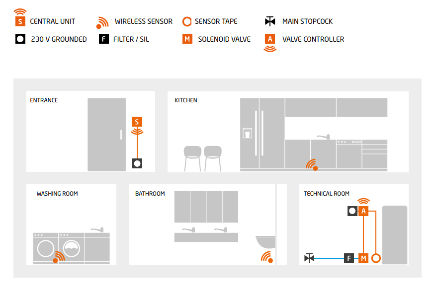
About the system
Waterguard (R) Smart Stop is a wireless system for stopping water leaks. It has a central unit that works together with wireless sensors and the wireless valve control.
All wireless components must be connected to the wireless central unit/control panel.
The unit has a function for delayed water stop. By activating DELAY, the water will be closed after 4 hours.
The wireless valve control has a 230V AC 10A socket for dishwashers, etc. In case of a leak the valve control will interrupt the power to this socket.*
* NB! THIS SOCKET IS NOT DEIGNED FOR CONNECTING WATER HEATERS. REF. NEK 400 - Norsk Elektronisk Komite (NEK)
The unit has a 1.5 meter cable with a 3-poled contact that is connected to the solenoid valve. When two valves are used, install the split cable with the original fastening screw for a solenoid valve contact on the valve control that is being switched over to the split cable contact. The enclosed long screw is used to fasten the valve control contact on the split cable male contact.
New functionality in this version
Safety function
The wireless valve control uses an internal safety function to prevent extracting the sensor cable by accident. Should this happen, a repeating 0,5 second signal will be heard, the LED indicator in the reset switch will flash a red light and the solenoid valve will close the water. When the contact is put in place again, the alarm will stop and the valve will open the water again.
If the wired sensor port is not in use, this function is deactivated.
If the sensor cable by accident is connected, and you later do not wish to use it (you need to disconnect it), this safety feature can be disabled by disconnecting the power, extracting the sensor cable and reconnect the power.
NB! Only the contact is monitored, if the sensor cable breaks - that will not trigger the alarm.
Auto-exercising valve
The wireless valve control is equipped with a function that automatically exercises the valve. This will prevent the pilot valve from getting stuck due to particles in the water. 1 second after it is powered, the unit will go through an exercising sequence where the pilot valve will open and close very fast, without influencing the flow of water.
The unit comes pre programmed with one exercising cycle every 24 hours.
This can be changed to the following frequency:
1 time every 24 hours - 1 time every week - no exercising of the valve.
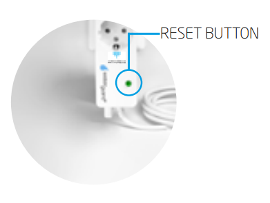
Reprogramming the exercising cycle
Hold in RESET button before the unit is powered, and keep holding it. After 20 seconds and audio signal/beep will be heard, and this will loop in 3 different steps until the RESET button is released after the sequence you prefer.
If the RESET button is let go after 1 beep, the valve will exercise every 24 hours.
If the RESET button is let go after 2 beeps, the valve will exercise every 7 days.
If the RESET button is let go after 3 beeps, the valve will not exercise.
To control the exercise status
Disconnect the power, after 10 seconds connect again.
The unit will now emit a number of beeps that corresponds to the chosen exercise frequence.
If you wish to change the exercise cycle, repeat the above explained programming sequence.
NB! When exercising is performed, the voltage will be cut in the units 230V ports. This cut lasts for about 300 ms, and might cause connected appliances to the operating status. Should this happen, it is not regarded a error on the valve control from Waterguard.
Registrating/Pairing wireless units
Wireless units
Prior to assembly, the wireless units must be paired with the central unit.
Connect the wireless central unit to power.
Connect the wireless valve control to power, connect the solenoid valve(s) to the valve control.
Open up the wireless sensor and insert batteries, do not put the lid back on.
1. On the central unit, push and hold RESET for about 2 seconds. At first, the panel will emit one beep and then two beeps. The unit is now ready for pairing with a wireless unit.
2. On the valve control, push and hold RESET until 2 beeps is heard. In a few seconds the units is paired, and they will emit another audio signal to confirm a successful registration.
3. Repeat part 1
4. Push the small switch on top of the cicuit board on the first wireless sensor for about 1 second. The central unit will emit audio signals, and a small light diode will flash for about 1,5 seconds. This indicates a successful pairing.
5. If more wireless sensors or wireless valve controls is to be paired, repeat the above described process. If a unit is registered more than once, it will be given an new ID every time.
If a unit is registered so many times that the number of beeps are too high, you can erase registrations. Erasing is done this way:
On the wireless central unit, press and hold RESET for about 5 seconds - until you hear 5 short beeps. By re-register a previously registered unit, they will get a new ID number starting on 1.
By failing to re-register, you risk having two wireless units with the same ID number. While not corrupting functionality, you will not be able to identify the triggered unit based on the number of beeps.
Installation instructions
Wireless central unit/control panel
1. The wireless central unit should be mounted in a concealed wallbox so that the enclosed power supply can be placed inside the box. This will ensure a good looking installation and stable power supply. It can also be placed inside one of the underlying switches' wallboxes, running the wires up from below the switches frame. Alternatively use a multibox, ex. Elko Multibox PFXP - El number 1223740.
2. The enclosed plug able power supply can be used instead of the internal one, but be aware that if this is unintentionally disconnected from the socket, the wireless sensor will no longer function.
Solenoid valve
The solenoid valve must be installed by a professional plumber, in a frost-free environment.
1. The solenoid valve is preferably mounted on the cold water intake, after the mains stopcock. If a fire hose is installed, the solenoid valve MUST be installed after the fire hose.
2. A filter MUST be installed where water can be contaminated by dirt or particles.
3. See to that sealing material used for installation does not enter the valve by assembly.
4. The solenoid may be installed horizontally or vertically. When installed horizontally, the electric coil must never face downwards. When mounted vertically, the electric outlet must always be on top of the coil.
5. The solenoid valve must be installed in the direction of water flow, see arrow on the housing.
Wireless valve control and sensor tape
1. The valve control is installed in a 230V grounded socket close to the valve and the monitored area.
2. Connect the Jack adapter to the valve control, and fasten it with a cable fastener to the floor.
3. The sensor tape is fastened to the Jack adapter with the blue tape strip on the end.
4. Remove the protective cover from the sensor tapes underside, and glue the tape to the floor/underlay where water from a leak may gather.
5. Connect the solenoid valve outlet to the valve control using the included screw. Tighten carefully to slightly squeeze the outlet to the valve coil.
Wireless sensor
On the floor
Can lie loose on the floor below the washing machine, refrigerator, etc. Remove the wall bracket to let the sensors get in touch with the underlay. Insert batteries according to instructions. The loose sensor tip can be folded under the sensor before the sensor is placed on the floor.
On wall
Using the included wall bracket, the sensor is easily mounted on the wall. Fasten the wall bracket so that the sensor tip barely touches the floor. Insert battery according to instructions. Insert the sensor tip in the bracket opening and click the sensor in place.
Using sensor tape
Open the wireless sensor by removing the top lid and remove batteries. Pull out the flat sensor tape, and push the new sensor tape all the way in (blue plastic facing down). Check that the small plastic pin in the sensor fits the hole in the tape. Insert batteries and put the lid back on. Remove the protective cover from the sensor tape and fasten it to the floor/underlay. The sensor tape can be cut to desired lengths. By cutting it in two, it can be connected to 2 units. Test the functionality by moistening some of the sensor points before you start using the system.
Start and test
Test the system before mounting it, using the central units ON/OFF switch. The valve should emit a distinctive clicking sound when it is being powered from the valve control.
Also, test the wireless sensors by moistening the sensor points. When these sensors sound an alarm, the central unit (when ON) will go to OFF, and the valve control will close the valve. The central unit and the valve control are reset by pushing RESET.
If the sensor cable on the valve control is activated, push RESET on the valve control once before the central unit can be reset by pushing RESET twice.
To reset the system, the moist that caused the alarm must be removed.
NB! When you are finished testing the system, thorough user instruction is mandatory.
1. Mount all units in their proper place and connect them to power. No signals should sound, except the start-up sound.
2. Open a tap to make sure the water is flowing. In the following tests, confirm that the water stops flowing from the open tap when the valve(s) close.
3. If you use the sensor port on the wireless valve control:
Test the safety function for the sensorcable by pulling it out.
- A 0.5 second repeating audio signal is heard.
- The LED indicator in the RESET button will flash in red and green.
- Water in the open tap will stop flowing. Control that the water starts flowing again when the sensor cable is put back in.
4. Wet one of the sensor points on the sensor tape using a moist cloth.
5. The valve control will now indicate a leak with repeating audio signals approximately every second. The LED indicator in the RESET button will emit a red light, and the valve will close the water.
6. Check that the water stops flowing from the open tap.
7. Push RESET once to stop the audible alarm, the water should remain closed.
8. Wait one minute while thoroughly drying the moist sensor point.
9. Now, stop the alarm by pushing the central unit's RESET button twice.
The audio signal from the central unit will stop, and LED OFF will change to LED ON.
10. Control that the water still flows from the open tap.
11. Moisten the sensor point on the first wireless sensor. The drop in the Waterguard logo will light ip red when moist is detected, and an alarm is being sent.
12. The water will be shut off, and the central unit will emit the number of beeps that corresponds with the triggered sensor. Wipe the sensor's moist parts thoroughly.
13. The wireless central unit can now be reset by pushing the RESET button twice.
14. Check that the water starts flowing from the tap.
15. Repeat the procedure with the other wireless sensors, and be sure to dry all sensor points thoroughly after the test.
Principle sketch
User manual
In case of alarm
1. The system has two types of alarms when detecting a leak:
2. A wireless sensor detection will only be alarmed in the wireless control panel.
3. A leakage detected by the valve control's sensor cable will be alarmed both on the valve control and on the control panel.
4. A leak alarm from a wireless sensor can only be reset/cancelled on the control panel. An alarm from the valve control's sensor cable must be reset/cancelled first on the valve control, then on the control panel.
5. If there is water on the valve control's sensor cable, the control will emit repeating 1 second alarm signals, and the RESET button will display a red light. The solenoid valve has now shut off the water flow. The central unit will sound an alarm, and LED OFF will light up.
6. If there is water on a wireless sensor, only the control panel will sound an alarm and light LED OFF.
The solenoid valve will shut the water supply.
7. When an alarm is triggered, this is either due to a water leak or other factors such as cleaning, etc.
8. Locate the water leak or spill, and dry up thoroughly.
9. The alarm signal from the units can be stopped by pushing the RESET button once. The solenoid valve will still be in closed position.
10. In case of a actual water leak, close the main stopcock and contact a plumber.
11. When the leak or spill is taken care of, be sure to carefully wipe the sensor points dry.
12. Push the RESET button and the light will change from red to blue. The solenoid valve will open.
Testing the system (at least twice a year)
1. Open the tap and let the water run.
2. With a wet cloth, moist one of the sensor points. The valve should now shut off the water flow.
3. Make sure the water in the open tap has stopped.
4. Dry the sensor point thoroughly with a cloth. Push the RESET button on the central unit to cancel the alarm. The alarm signal should now stop, and the LED should change from red to blue. The valve will open again.
5. Test all the wireless sensors and sensor cables. If the sensor port on the valve control is activated, the valve control must be reset before the central unit can be reset.
User manual
Battery change
The included sensor batteries has an expected lifetime of approximately 5 years.
We recommend a battery change after maximum 5 years. Sensors with weak batteries may, if placed far away, not connect with the central unit.
In case of low battery status, the central unit will warn with an audio signal. The unit will remain in its initial state without closing the solenoid valve. The number of audio signals from the central unit will correspond with the sensors ID number when installed. The alarm is repeated every 25 seconds. Reset the alarm with a brief push on the RESET button. Take note of the number of signals/which sensor has triggered before you reset the alarm.
1. Remove the sensor from the wall bracket by pulling it approximately 5mm upwards and then pulling it straight out. Remove the top lid by using the small slots on the side.
2. Remove the batteries and insert new of the same type (AAA). Push the switch (marked with red on pic 2) and check that the LED on the right side starts flashing. Put the lid back on.
3. Test the sensor: (see also 4 below)
Place a moist cloth or finger on one of the sensor points, the alarm should immediately be released. After cancelling the alarm, carefully dry the moist sensor point.
4. Put the sensor back in the bracket. This test can also be done after the sensor is mounted, by moistening the sensor cable.
Comments
0 comments
Please sign in to leave a comment.